
Plastic Corrugated Pipe Extrusion: Forming Routes and Quality Control
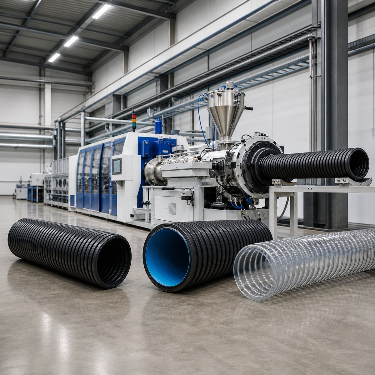
Plastic corrugated pipe combines high structural stiffness with efficient material use and, depending on the design, excellent flexibility. This makes it useful in underground drainage, cable protection, automotive wire harnesses, post-tensioning ducts, suction hoses, and many other applications.
Producing the profile consistently is not a single-process problem. It requires the resin, screw, die head, forming mechanism, cooling path, haul-off, and downstream handling to operate as one system. This guide explains the three main forming routes used by Wings Plastic and shows how to connect product requirements with the correct production-line configuration.
1. Why Corrugated Pipe Requires Dedicated Forming Technology
A solid-wall pipe relies primarily on wall thickness. A structured-wall corrugated pipe uses a smooth inner wall, a periodic outer profile, or a flexible spiral reinforcement to place material where it contributes most to performance.
The structure can provide three practical benefits:
- Efficient stiffness: corrugations increase the section’s moment of inertia without requiring the mass of a solid wall.
- Lower material demand: for a specified ring-stiffness class, a well-designed structured wall can reduce weight per metre.
- Combined functions: a double-wall corrugated pipe can use its smooth bore for hydraulic performance and its profiled outer wall for resistance to external load.
These benefits only appear when the profile is fully formed, the wall distribution is stable, and the pipe is cooled without distortion. The corrugator and cooling system are therefore as important as the extruder.
2. Three Forming Mechanisms
Closed mould blocks with vacuum or air pressure
In block forming, matched mould blocks close around the molten tube. Vacuum channels pull the melt into the corrugation cavities, internal air pressure pushes it against the mould surface, or both methods operate together.
Vacuum forming is useful for small profiles that require accurate replication. Air forming is widely used for higher-output and larger-diameter pipe. In double-wall production, the die core, internal air, and calibration water sleeve must also keep the inner wall smooth and centred.
Rotating vacuum mould for spiral profiles
A rotating tubular mould contains an internal spiral profile and vacuum grooves. Low-viscosity melt enters the mould, follows the rotating profile under vacuum, and cools into a continuous spiral structure.
This mechanism suits products such as corrugated optical duct (COD) outer sheaths and some post-tensioning ducts. A flat post-tensioning duct made by this route is normally formed first as a round spiral pipe and then flattened. A mould-block corrugator can instead form an accurately shaped flat duct directly.
Spiral winding and interlocking
Flexible hose is commonly made by continuously winding an extruded strip or profile around a mandrel. A rigid spiral can be bonded to a soft wall, or adjacent profiles can be locked together with heat or adhesive.
Typical examples include PVC spiral suction hose, EVA/LLDPE vacuum-cleaner hose, and PE/PP spiral wrap. In these products, bonding temperature, winding pitch, and material compatibility matter more than mould-block motion.
3. The Three Production Routes
Block Corrugator Way
The Block Corrugator Way is the main route for single-wall corrugated pipe (SWC) and double-wall corrugated pipe (DWC). Mould blocks circulate, close around the melt, form the profile, open, and return to the inlet.
Representative applications include:
- High-speed water-cooled DWC lines for approximately 40–180 mm pipe.
- Large-diameter water-cooled DWC lines covering product ranges up to 1600 mm.
- Air-cooled aluminium-mould and steel-mould DWC lines for selected output and investment requirements.
- SWC lines starting from very small internal diameters for electrical conduit, automotive harness tube, and medical hose.
Within this route, the block transport system is critical. A gear-and-track corrugator lets the blocks run independently on precision tracks and supports an efficient 360-degree indirect water circuit around the track. A gear-and-chain-link machine connects blocks through hinges; wear in those joints can introduce alignment error, and the linkage restricts the cooling layout.
Buyers should inspect the internal mechanism rather than judge a corrugator by its external enclosure. A modern cover does not identify the block transport or cooling method.
Rotation Corrugator Way
The Rotation Corrugator Way uses a rotating vacuum mould for continuous spiral forming. It is intended for special low-viscosity and spiral-structure products rather than conventional matched-block DWC production.
For COD pipe, an integrated line can first extrude low-friction inner ducts and then enclose several ducts in a corrugated outer sheath. For post-tensioning duct, rotational forming offers economical mould changes for round pipe, while direct mould-block forming is preferred when a stable flat profile and resistance to shape recovery are essential.
Flexible Winding Corrugator Way
The Flexible Winding Corrugator Way forms a hose by winding and bonding extruded materials. A typical PVC spiral-reinforced hose uses one extruder for the rigid reinforcement and another for the soft wall, arranged around an adjustable rotating former. Vacuum-cleaner hose can use a hot-melt interlock, while spiral protective wrap is formed from an extruded strip and cut or wound to its final size.
4. Five Production-Line Elements That Control the Result
1. Extruder and screw design
PVC and PE/PP require different thermal and shear histories.
- PVC is heat sensitive. Excessive residence time or shear can cause discoloration and degradation. PVC systems normally use a shorter screw geometry, carefully controlled compression, and appropriate venting. Conical twin screws are common for dry blend, while precision small-diameter SWC production may use a dedicated stable single-screw system.
- PE and PP are crystalline polyolefins. They generally benefit from a longer screw, sufficient compression, and a barrier or mixing section that produces a uniform melt.
PVC should not be processed through a high-shear PE/PP screw merely by changing temperature settings. PE and PP are more compatible with one production platform, although recipes, temperatures, and speeds must still be adjusted.
2. Die head and centring
A straight-out die provides balanced flow for standard round pipe. An L-shaped die can shorten the line and support special inline processes. A multilayer DWC die contains separate flow channels plus air and cooling passages.
Regardless of design, the die must distribute melt evenly. Die-lip clearance, core position, melt pressure, and the water sleeve determine inner-wall thickness and concentricity. Online wall adjustment is especially valuable during product changeover.
3. Mould-block material and cooling
Nitrided 40Cr steel provides wear resistance for small precision profiles. Aluminium and aluminium alloys reduce moving mass and transfer heat efficiently in high-output and large-diameter systems.
Cooling paths differ by platform:
- High-speed SWC track machines use efficient indirect water cooling through the track.
- Entry-level DWC systems may combine water and air cooling.
- Air-cooled cast-aluminium blocks simplify utilities for moderate output.
- High-speed DWC aluminium blocks can contain direct internal water channels for the shortest heat-transfer path.
4. Stable cooling utilities
Forming speed is limited by how fast the melt can solidify without stress or deformation. Water flow, pressure, temperature, nozzle balance, vacuum stability, and chiller capacity must therefore be treated as process variables, not auxiliary details.
5. Haul-off, cutting, and winding
Downstream equipment must match the corrugator. For example, producing 100-m coils at 30 m/min requires a coil change approximately every 3.3 minutes. If the operator or winder cannot complete the cycle, pipe accumulates on the floor and deforms.
The useful speed is the speed the entire line can sustain. A moderate forming speed paired with automatic cutting and a suitable single- or double-station winder may deliver better real output than an unmatched high-speed corrugator.
5. Systematic Troubleshooting of Common Defects
Change only one parameter at a time and record the result.
- Rough outer wall or incomplete corrugation: check premature cooling, mould contamination, vacuum or air pressure, and melt temperature. Clean mould grooves with a suitable non-damaging tool and adjust temperature in small steps.
- Bubbles or burnt areas on the inner wall: check wet resin, excessive temperature, long residence time, and unstable forming air. Dry the resin and correct temperature or pressure gradually.
- Uneven wall thickness: measure at 0°, 90°, 180°, and 270°. Check die-lip clearance, die centring, mould vibration, and the water sleeve before changing throughput.
- Insufficient ring stiffness: verify profile depth, rib material distribution, weight per metre, block wear, and cooling conditions. Increasing total wall thickness without locating the structural weakness can waste resin.
- Pipe curvature: inspect asymmetric spray cooling, left/right haul-off pressure, block alignment, and the production-line centreline.
A five-minute shift-start check should cover actual versus set temperature, melt-pressure trend, screen condition, water and vacuum flow, resin contamination, deposits on blocks and haul-off surfaces, abnormal bearing or pump noise, and retention of an approved reference sample.
6. Standards and Export Compliance
Product standards depend on application and destination:
- Ring stiffness is commonly tested under ISO 9969 and expressed in classes such as SN4, SN8, or SN16.
- EN 13476 covers many European PP/PE structured-wall piping applications; ISO 21138 addresses non-pressure structured-wall drainage and sewerage systems.
- GB/T 19472 applies to relevant structured-wall pipe in China.
- Electrical conduit projects may refer to IEC 61386 and project-specific flame, compression, and impact requirements.
- Plastic post-tensioning ducts should be checked against the applicable project specification; EN 523 concerns steel strip sheaths and is not a general plastic-duct product standard.
- Machinery supplied to the European market must be assessed against applicable CE requirements, including machinery safety obligations.
Always confirm the current product standard, test method, and acceptance criteria with the customer or certification body before finalizing mould geometry and line capacity.
7. A Practical Selection Framework
- Define the product: DWC drainage pipe, high-speed SWC conduit, integrated COD, dimensionally stable post-tensioning duct, or a flexible wound hose.
- Define the size range: minimum and maximum diameter determine the corrugator frame, block series, and die package.
- Define sustainable output: extruder capacity can range from small precision systems to heavy-duty lines above 1000 kg/h, but cooling and downstream handling must support that output.
- Match the forming route: choose block forming, rotation forming, or winding according to profile and material—not according to machine appearance.
- Calculate total ownership cost: include mould sets, energy, chiller demand, weight-per-metre efficiency, operator count, changeover time, spare parts, and maintenance.
For the product families described here, review the double-wall corrugator range, single-wall corrugators, and other corrugated-pipe solutions before defining a factory layout.
8. Conclusion
Corrugated-pipe forming combines polymer processing, precision mechanics, heat transfer, and downstream automation. Block forming depends on accurate block guidance and effective cooling. Rotation forming depends on stable spiral geometry and coordinated integration. Flexible winding depends on bonding, pitch, and material compatibility.
Across all three routes, stable production comes from the same foundation: a screw matched to the resin, a uniformly balanced die, and a cooling system able to remove heat at the required rate.