
Single Wall Pipe Corrugator Structure: Circulation, Drive and Water Cooling
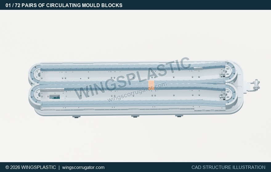
To understand a single wall pipe corrugator, start with two questions: how do the mould blocks circulate, and how does the forming section release heat? Using the WingsPlastic 72-pair mould block structure as an example, these eight animations follow the drive and cooling-water paths to show how the components work together.
Text, images and structural demonstrations: Wings Plastic.
1. How 72 mould block pairs complete a circuit
This forming unit has 72 pairs of mould blocks, or 144 half-moulds. The two sets of half-moulds each follow a closed path. They pair up along the straight working section to form a continuous series of cavities, separate at the outlet and return to the inlet for the next cycle.
View the working section, outlet separation area and return section as one circuit. Pairing and separation take place at different points. The return section brings the blocks back, while the straight working section provides the continuous corrugated forming profile.
Fig. 1 · Circulation of 72 mould block pairs
Still preview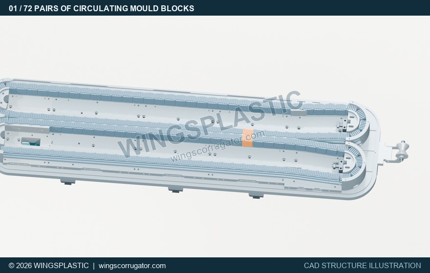
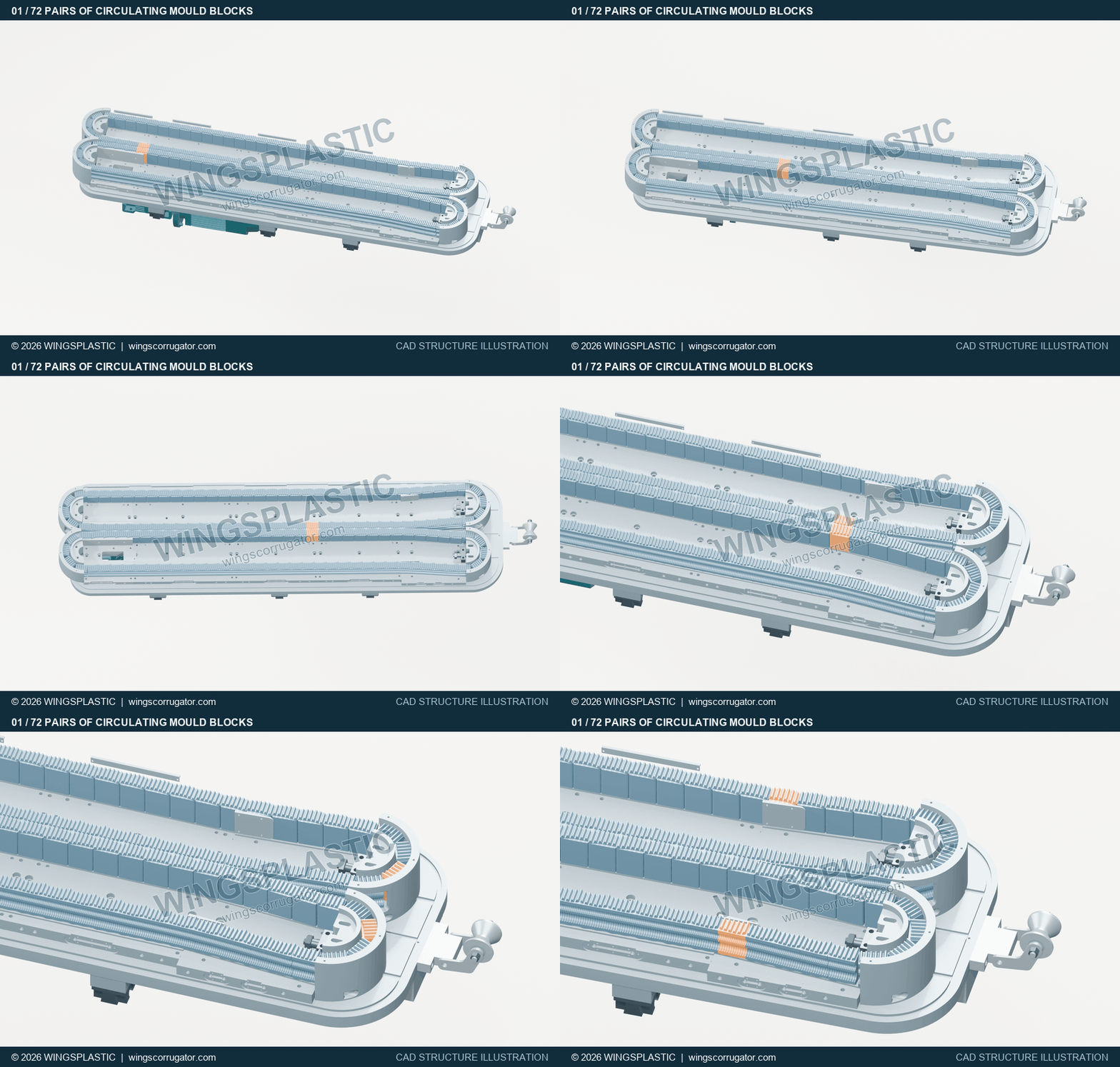
72 mould block pairs, or 144 half-moulds, follow two closed paths: pairing in the working section, separating at the outlet and returning to the inlet.
Duration approx. 6.4 s · Text, images and structural demonstrations: Wings Plastic2. How the motor and reducer deliver power to the drive shaft
The drive path starts at the motor and reducer. Sprockets and a duplex roller chain transmit rotation from the reducer output to the forming unit's drive shaft. Plates, rollers and pins form articulated chain links that run around the closed path between the sprockets.
The animation shows the chain connection at the existing sprocket positions. When reviewing an equipment proposal, follow the reducer output, chain and drive shaft in sequence. The actual chain type, length and tensioning arrangement depend on the equipment drawings and parts list.
Fig. 2 · Motor, reducer and chain drive
Still preview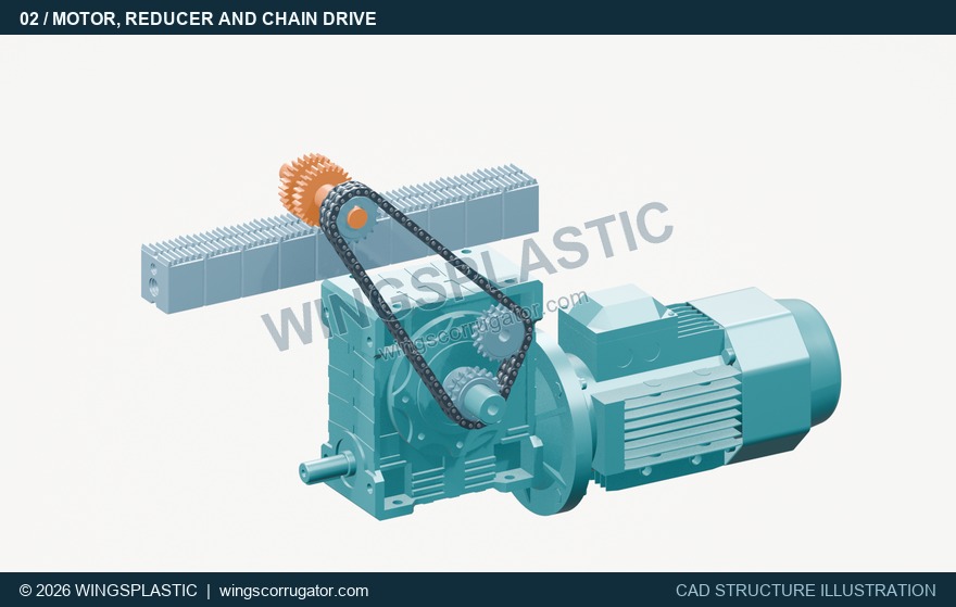
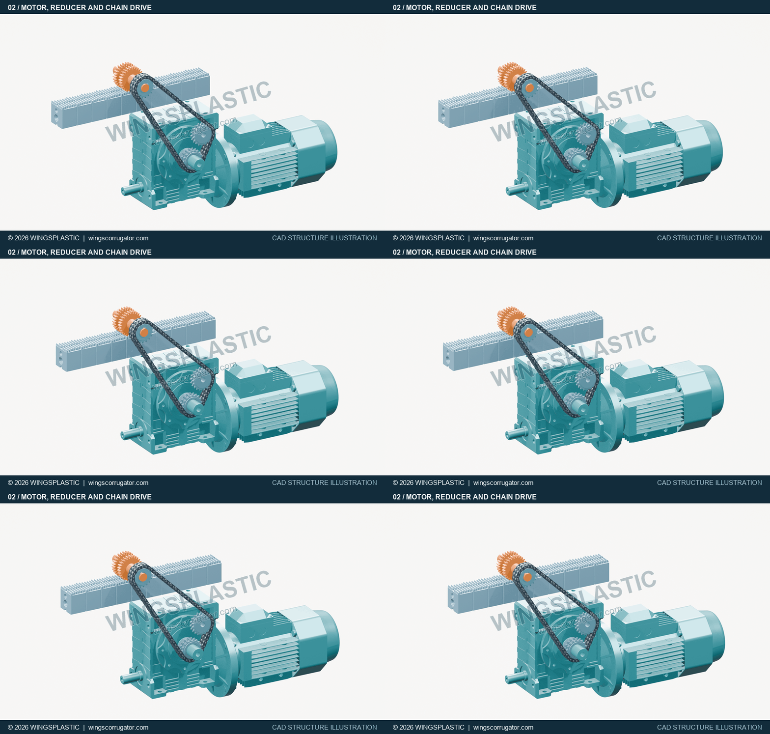
The motor and reducer transmit rotation to the forming unit's drive shaft through sprockets and a duplex roller chain.
Duration approx. 3.5 s · Text, images and structural demonstrations: Wings PlasticFig. 3 · Duplex roller chain engagement
Still preview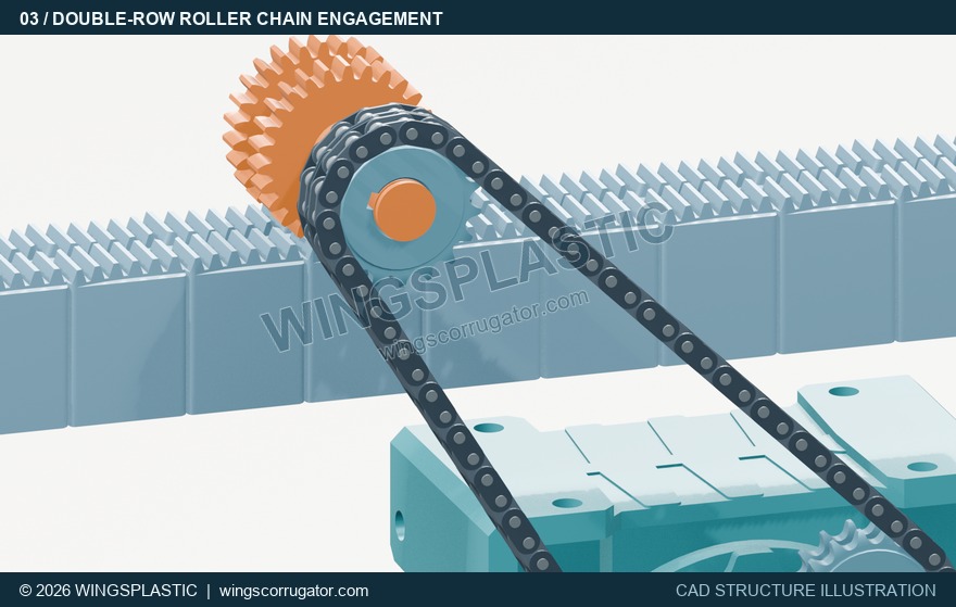
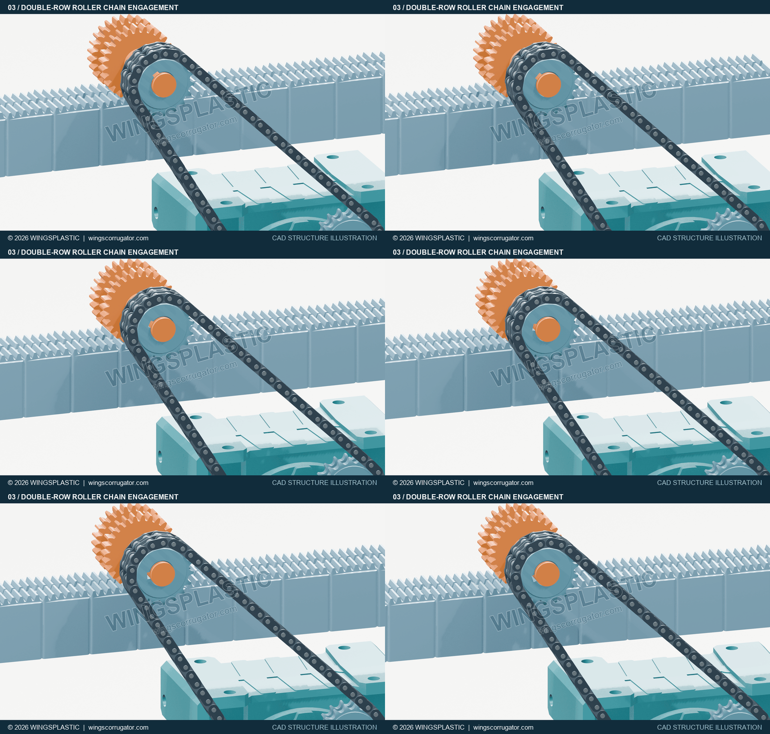
Plates, rollers and pins form articulated links that engage with the sprockets and circulate. The chain type, length and tensioning arrangement follow the equipment drawings.
Duration approx. 3.5 s · Text, images and structural demonstrations: Wings Plastic3. Gears and racks turn rotation into mould block travel
Two coaxial gear rings on the drive shaft engage with the racks on the two sides. As the gears rotate, their teeth drive the racks along the direction of travel, converting shaft rotation into mould block movement.
Together with the chain-drive view, this gives the complete power path: motor, reducer, chain, drive shaft and gears, then the mould block racks. Besides the drive components, note the relative positions of the gear rings and the racks on both sides.
Fig. 4 · Gear-and-rack mould block drive
Still preview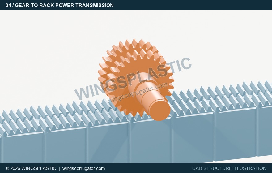
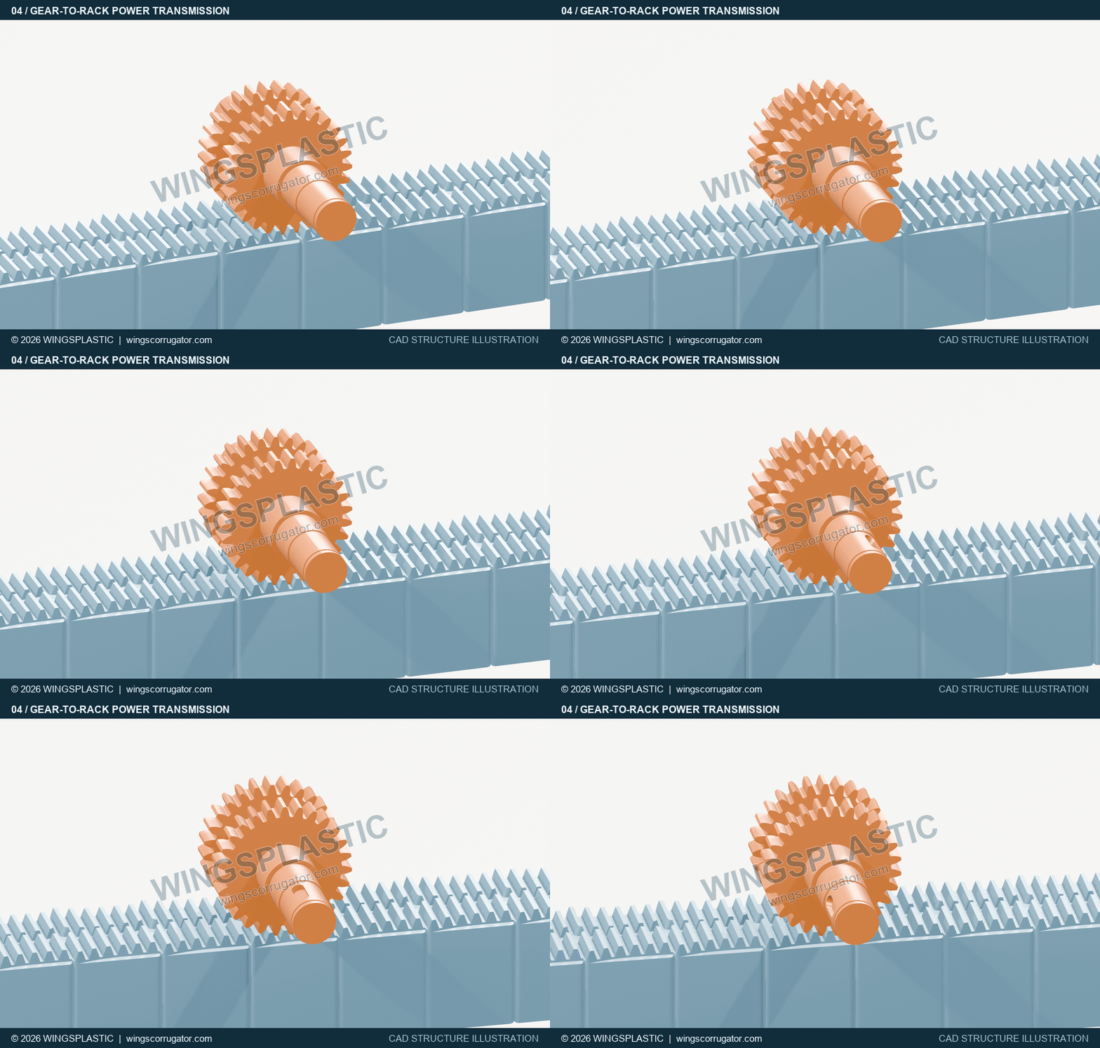
Two coaxial gear rings on the drive shaft drive the mould block racks on both sides, converting rotation into forward travel.
Duration approx. 6.4 s · Text, images and structural demonstrations: Wings Plastic4. Cooling water first flows inside the base plates
Cooling water enters the forming base plates and flows through their interconnected internal passages. Besides mounting and support, the solid plate bodies conduct heat away from the bottoms of the mould blocks, cooling them indirectly. Both the internal passages and the surrounding plate material matter.
A partial cutaway reveals the passages while retaining the plate edges and thickness. Blue areas represent the internal water space. Water circulates inside the base plates, which connect to the side cooling plates through transfer ports.
Fig. 5 · Internal water passages in the forming base plates
Still preview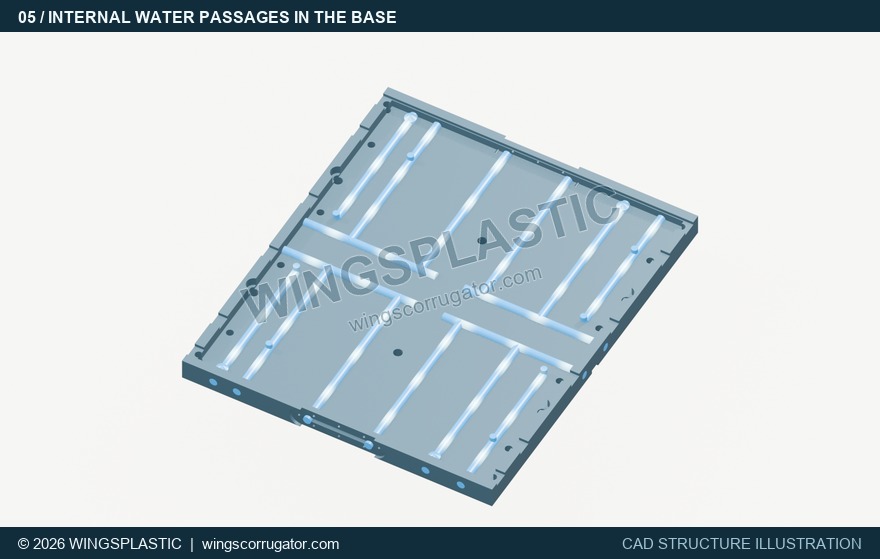
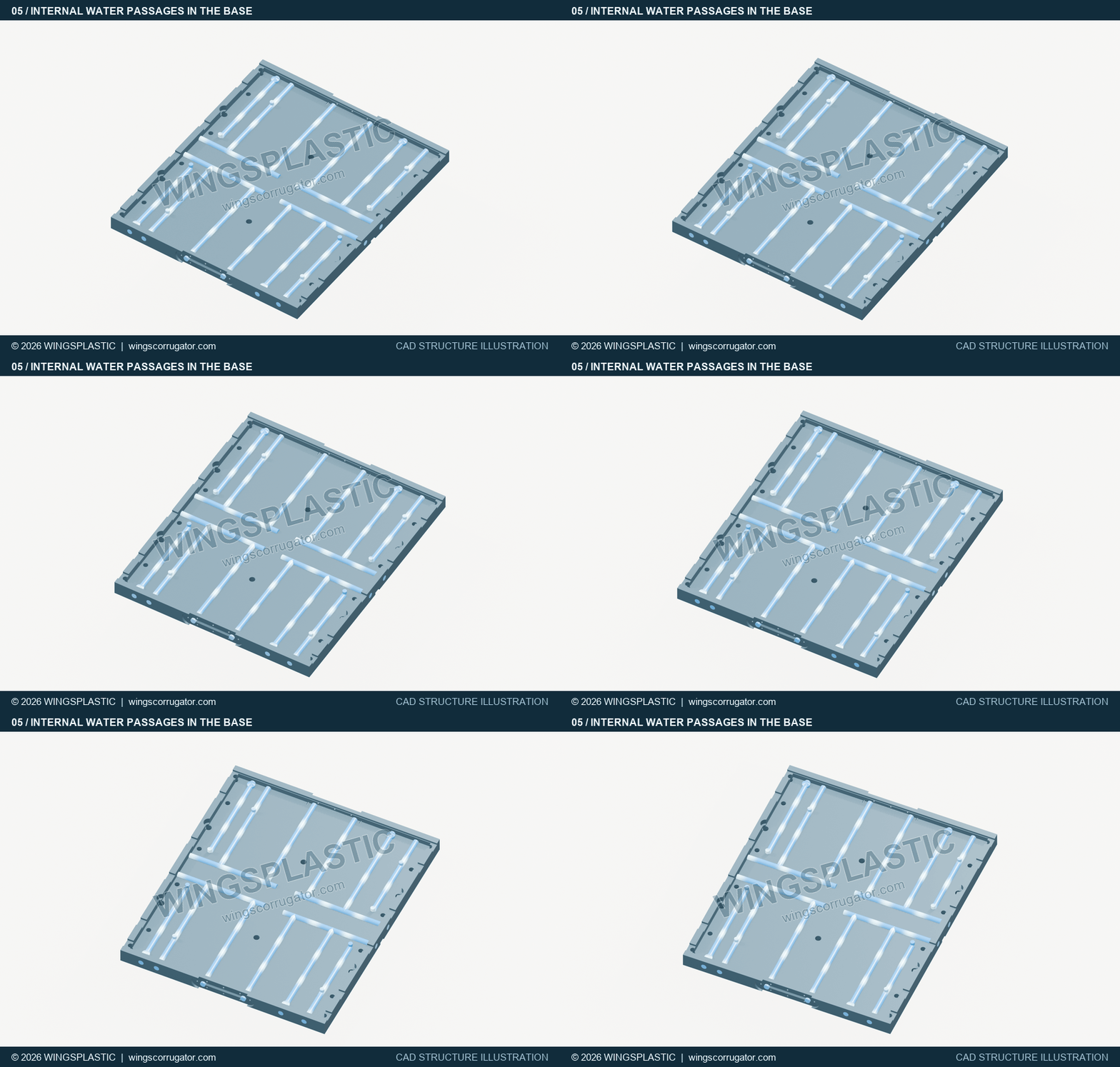
A partial cutaway shows interconnected cooling passages inside a base plate. Water cools the plate, which indirectly removes heat from the mould block bottoms.
Duration approx. 6.4 s · Text, images and structural demonstrations: Wings Plastic5. Side cooling plates: water passes from the large chamber to the small chamber
Water enters the large chamber of a side cooling plate through a transfer port in the base plate. Once the large chamber fills, water passes over the top of the baffle through the connecting opening into the small chamber, then returns to the forming base plate through another transfer port. The side plates cool the sides of the mould blocks.
To follow the flow, identify the large chamber, small chamber, top connecting opening and inlet/return ports. Assembly orientation changes their left-right positions in the image, but not the large-chamber-first sequence. The filling animation lets you inspect these connections step by step.
Fig. 6 · Side cooling plate: large chamber, small chamber and return
Still preview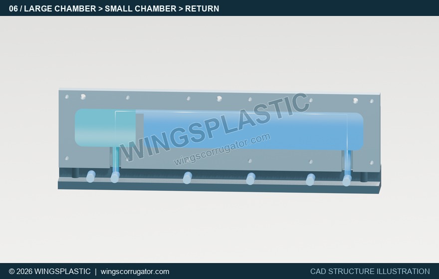
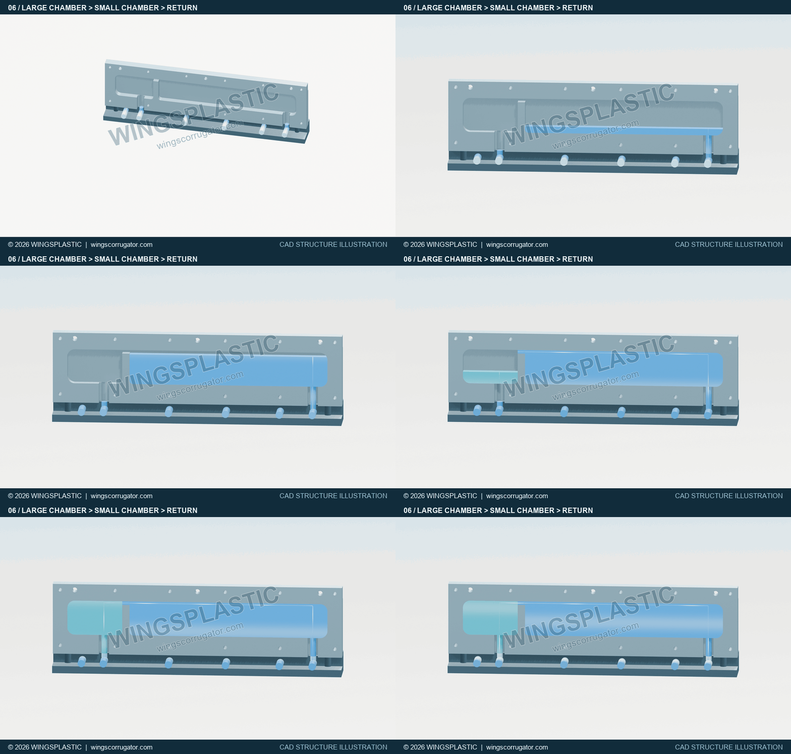
Water enters the large chamber from the base-plate transfer port, crosses the opening above the baffle into the small chamber and returns through another port. This sequence is shown at about 2× speed, not the actual filling time.
Duration approx. 6.9 s · Text, images and structural demonstrations: Wings Plastic6. From individual passages to the complete forming unit
Base-plate passages and side-plate chambers are distributed along the forming section. This structure has 5 base plates and 14 side cooling plates. Internal water passages cover the front drive section, middle sections and separation-section base plate. The side plates form 7 pairs arranged symmetrically about the centre plane.
The animation separates the mould blocks from the cooling structure to reveal the water passages. This is an explanatory view, not the assembled position during operation.
Fig. 7 · Overall cooling arrangement in the forming section
Still preview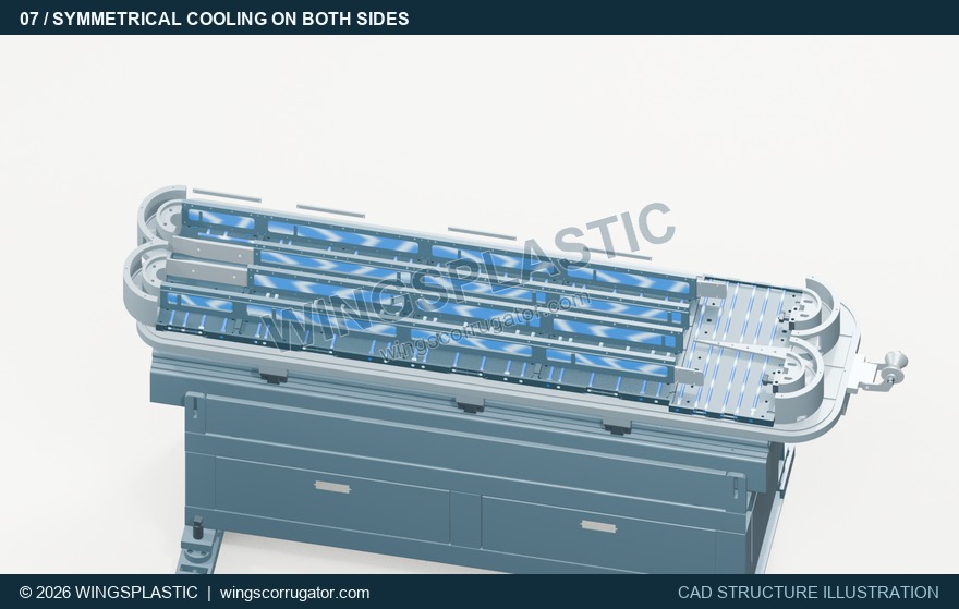
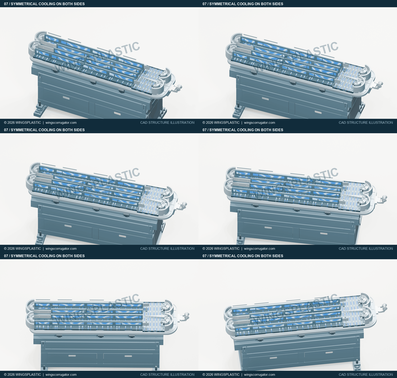
A whole-unit cutaway shows base-plate passages and side cooling plates. Mould blocks are shown apart from the cooling structure to reveal the passages, not in their operating assembly positions.
Duration approx. 6.4 s · Text, images and structural demonstrations: Wings Plastic7. The cavities connect drive, circulation and cooling
When a pair of half-moulds closes, their internal profiles form the moulding space. The open half-mould view reveals the corrugated grooves and mating faces. The cavities, product sizes and forming channels depend on the fitted mould configuration.
During operation, the drive moves the mould blocks around the circuit. Half-moulds pair up in the working section while base plates and side plates remove heat. At the outlet, the blocks separate and return. These parts together explain how movement, cavities and cooling cooperate in the forming unit.
Fig. 8 · Half-mould cavities and mating faces
Still preview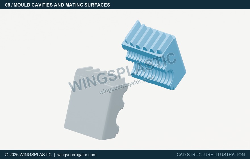
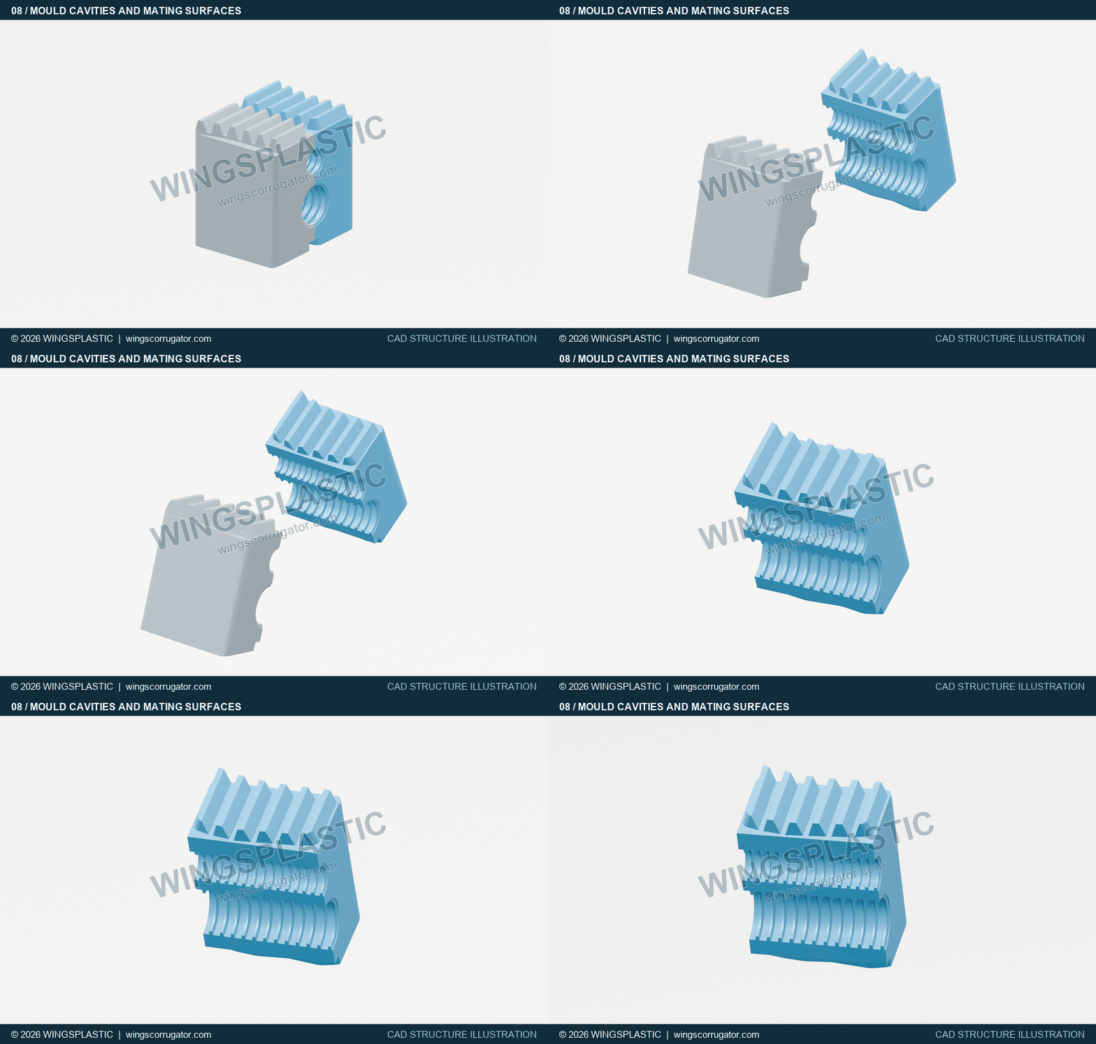
The open half-moulds reveal the corrugated cavity profiles and mating faces. Product dimensions and cavity arrangements depend on the installed moulds.
Duration approx. 4.4 s · Text, images and structural demonstrations: Wings Plastic